
Installation
This Quick Installation Guide covers Mango Power S and S Pro (US). Safety, error codes, and replacement procedures are in the User Manual. Electrical ratings from the datasheet are in Specifications.
Pre-installation
Section titled “Pre-installation”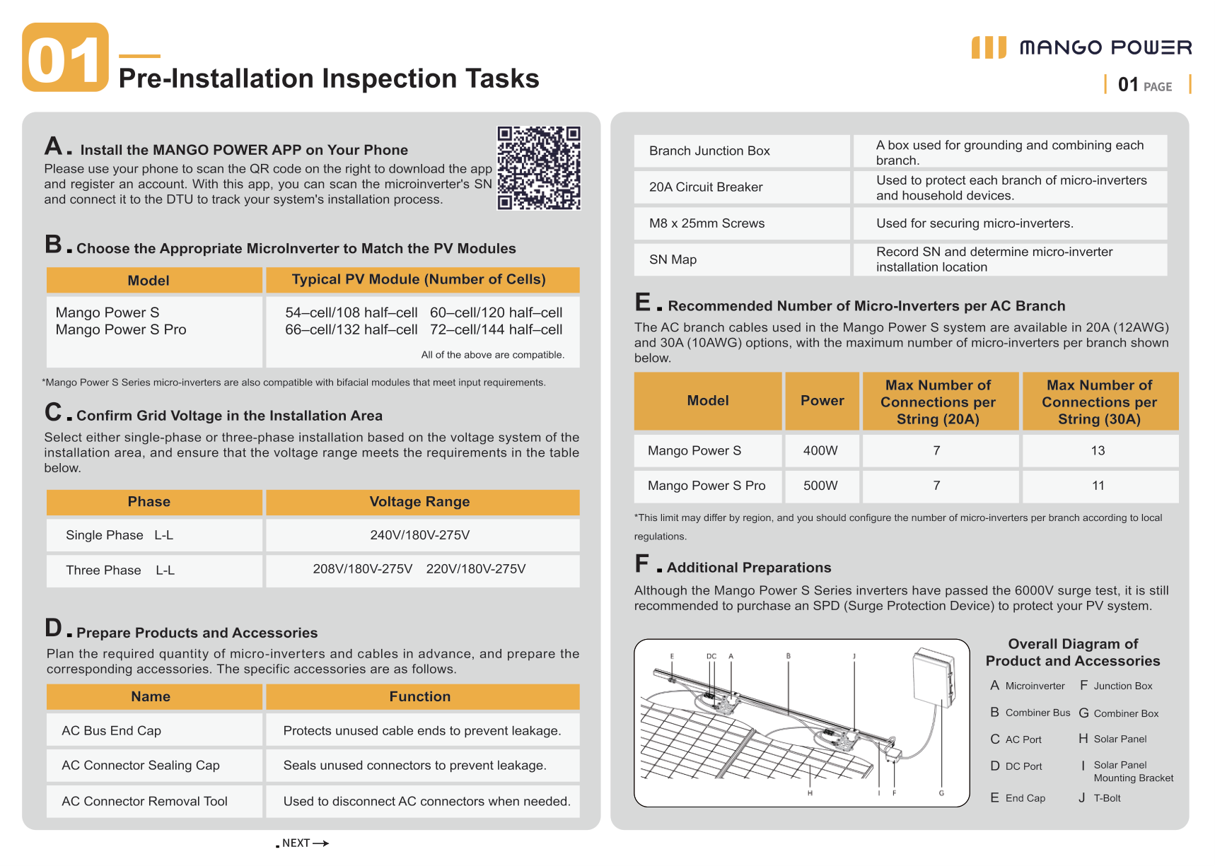
Install the MANGO POWER app
Section titled “Install the MANGO POWER app”Scan the QR code in the guide to download the app and register an account. Use the app to scan the microinverter serial number (SN) and connect to the DTU to track installation.
Match the microinverter to the PV module
Section titled “Match the microinverter to the PV module”Mango Power S and S Pro are compatible with typical PV modules of 54-cell/108 half-cell, 60-cell/120 half-cell, 66-cell/132 half-cell, and 72-cell/144 half-cell. They are also compatible with bifacial modules that meet the input requirements.
Confirm grid voltage
Section titled “Confirm grid voltage”Select single-phase or three-phase installation according to the local voltage system.
| Phase | Voltage range |
|---|---|
| Single phase L-L | 240V / 180V-275V |
| Three phase L-L | 208V / 180V-275V, 220V / 180V-275V |
Prepare products and accessories
Section titled “Prepare products and accessories”| Name | Function |
|---|---|
| AC bus end cap | Protects unused cable ends to prevent leakage |
| AC connector sealing cap | Seals unused connectors to prevent leakage |
| AC connector removal tool | Disconnects AC connectors when needed |
| Branch junction box | Grounding and combining each branch |
| 20A circuit breaker | Protects each branch of microinverters and household devices |
| M8 × 25mm screws | Secures microinverters |
| SN map | Records SN and installation location |
AC junction boxes, terminal blocks, combiner boxes, and circuit breakers are provided by the installer based on site conditions.
Recommended number of microinverters per AC branch
Section titled “Recommended number of microinverters per AC branch”AC branch cables are available as 20A (12AWG) and 30A (10AWG).
| Model | Power | Max connections per string (20A) | Max connections per string (30A) |
|---|---|---|---|
| Mango Power S | 400W | 7 | 13 |
| Mango Power S Pro | 500W | 7 | 11 |
This limit may differ by region. Follow local regulations.
Additional preparations
Section titled “Additional preparations”The microinverters have passed a 6000V surge test. Purchasing an SPD (surge protection device) is still recommended to protect the PV system.
Installation steps
Section titled “Installation steps”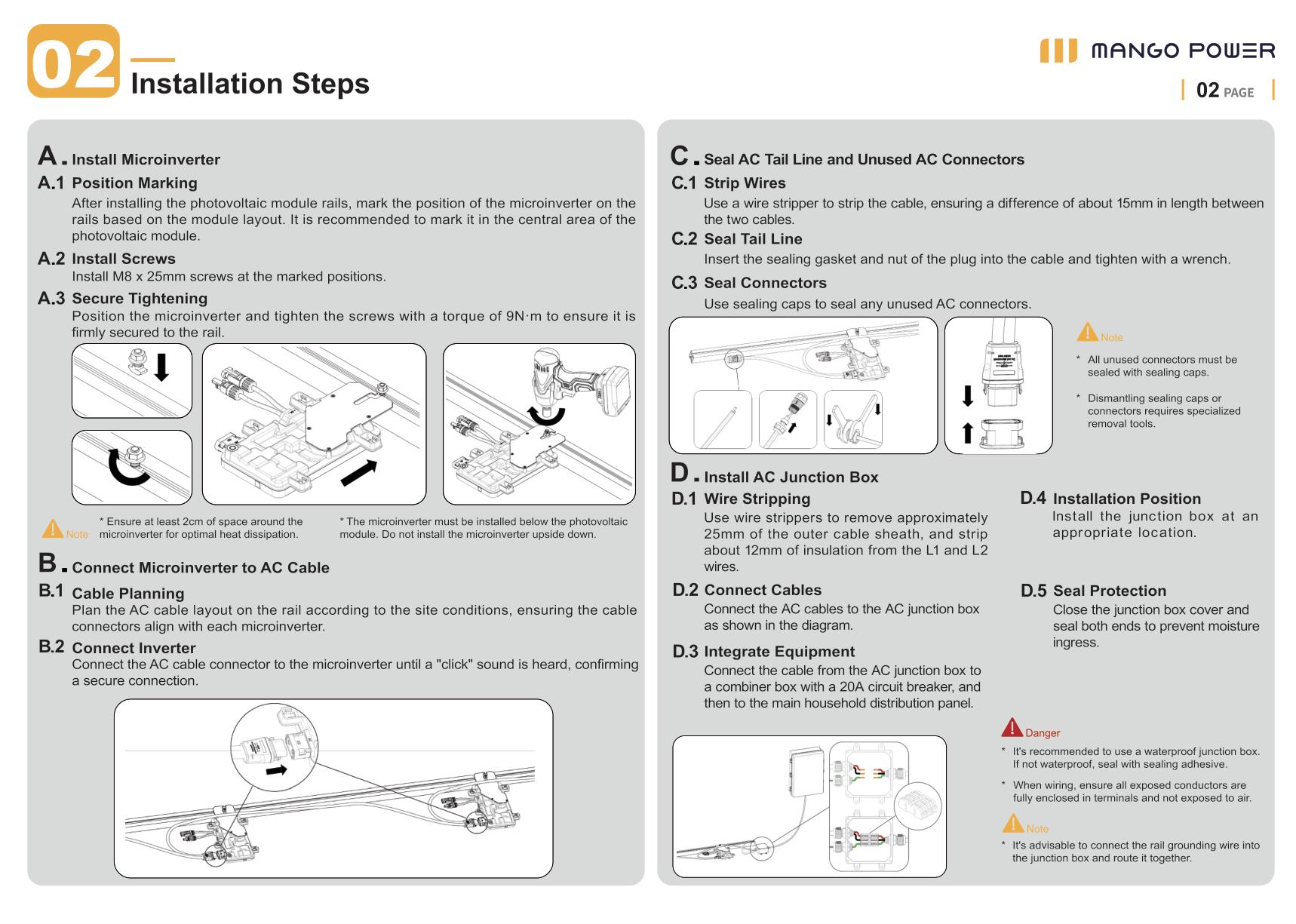
A. Install the microinverter
Section titled “A. Install the microinverter”- After installing the PV module rails, mark the microinverter position on the rails according to the module layout. Mark the central area of the PV module.
- Install M8 × 25mm screws at the marked positions.
- Position the microinverter and tighten the screws to 9 N·m.
Keep at least 2 cm of space around the microinverter for heat dissipation. Install the microinverter below the PV module. Do not install it upside down.
B. Connect the microinverter to the AC cable
Section titled “B. Connect the microinverter to the AC cable”- Plan the AC cable layout on the rail so connectors align with each microinverter.
- Connect the AC cable connector to the microinverter until a click confirms a secure connection.
C. Seal the AC tail line and unused AC connectors
Section titled “C. Seal the AC tail line and unused AC connectors”- Strip the cable so the two internal wires differ in length by about 15 mm.
- Insert the sealing gasket and nut of the plug into the cable and tighten with a wrench.
- Seal unused AC connectors with sealing caps.
All unused connectors must be sealed. Removing sealing caps or connectors requires specialized removal tools.
D. Install the AC junction box
Section titled “D. Install the AC junction box”- Remove about 25 mm of the outer cable sheath and strip about 12 mm of insulation from the L1 and L2 wires.
- Connect the AC cables to the AC junction box.
- Connect the cable from the AC junction box to a combiner box with a 20A circuit breaker, then to the main household distribution panel.
- Install the junction box at an appropriate location.
- Close the junction box cover and seal both ends to prevent moisture ingress.
Use a waterproof junction box. If it is not waterproof, seal it with sealing adhesive. Keep all exposed conductors fully enclosed in terminals. Connect the rail grounding wire into the junction box and route it together.
E. Organize AC cables
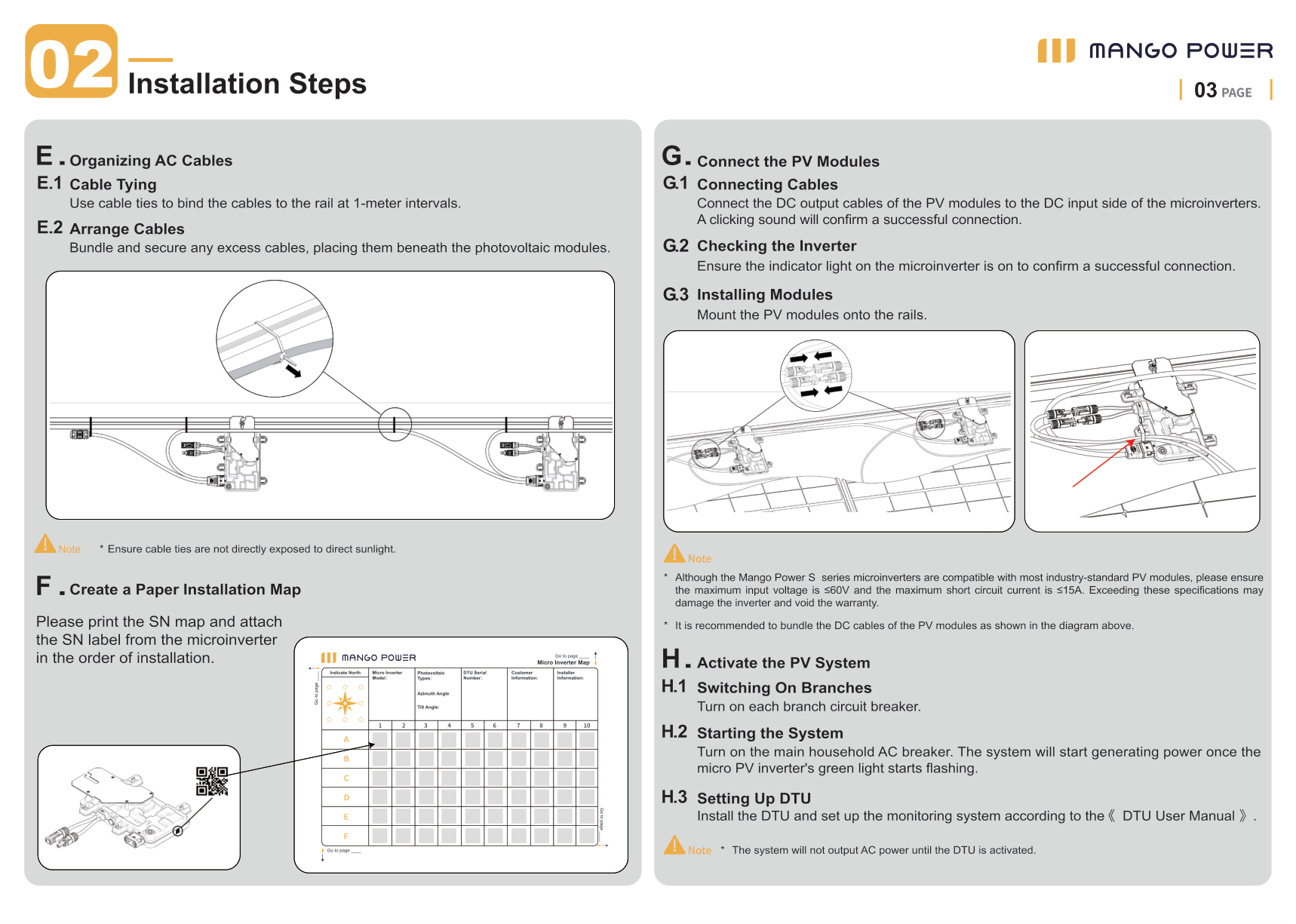
Section titled “E. Organize AC cables”- Use cable ties to bind the cables to the rail at 1-meter intervals.
- Bundle and secure excess cables beneath the PV modules.
Do not leave cable ties directly exposed to sunlight.
F. Create a paper installation map
Section titled “F. Create a paper installation map”Print the SN map and attach the SN label from each microinverter in the order of installation.
G. Connect the PV modules
Section titled “G. Connect the PV modules”- Connect the DC output cables of the PV modules to the DC input of the microinverters. A click confirms a successful connection.
- Confirm the indicator light on the microinverter is on.
- Mount the PV modules onto the rails.
Although the S series microinverters are compatible with most industry-standard PV modules, keep maximum input voltage ≤60V and maximum short circuit current ≤15A. Exceeding these specifications may damage the inverter and void the warranty. Bundle the DC cables as shown in the guide.
H. Activate the PV system
Section titled “H. Activate the PV system”- Turn on each branch circuit breaker.
- Turn on the main household AC breaker. The system starts generating power once the microinverter green light starts flashing.
- Install the DTU and set up the monitoring system according to the DTU user manual.
The system will not output AC power until the DTU is activated.
LED indicator
Section titled “LED indicator”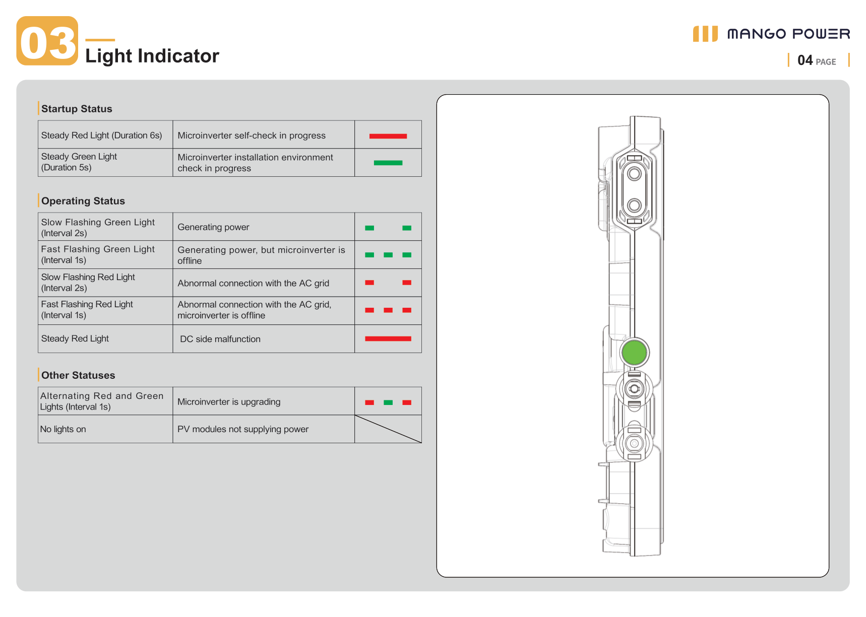
| LED behavior | Meaning |
|---|---|
| Steady red (6 s) | Self-check in progress |
| Steady green (5 s) | Installation environment check in progress |
| Slow flashing green (interval 2 s) | Generating power |
| Fast flashing green (interval 1 s) | Generating power, but the microinverter is offline |
| Slow flashing red (interval 2 s) | Abnormal connection with the AC grid |
| Fast flashing red (interval 1 s) | Abnormal connection with the AC grid; microinverter is offline |
| Steady red | DC side malfunction |
| Alternating red and green (interval 1 s) | Upgrading |
| No lights | PV modules not supplying power |
Wiring diagrams
Section titled “Wiring diagrams”The AC junction box, terminal blocks, combiner box, and circuit breakers are provided by the installer based on site conditions.
Single-phase
Section titled “Single-phase”Before installation, confirm the household grid is a single-phase system. Have a professional install the PV system according to this diagram.
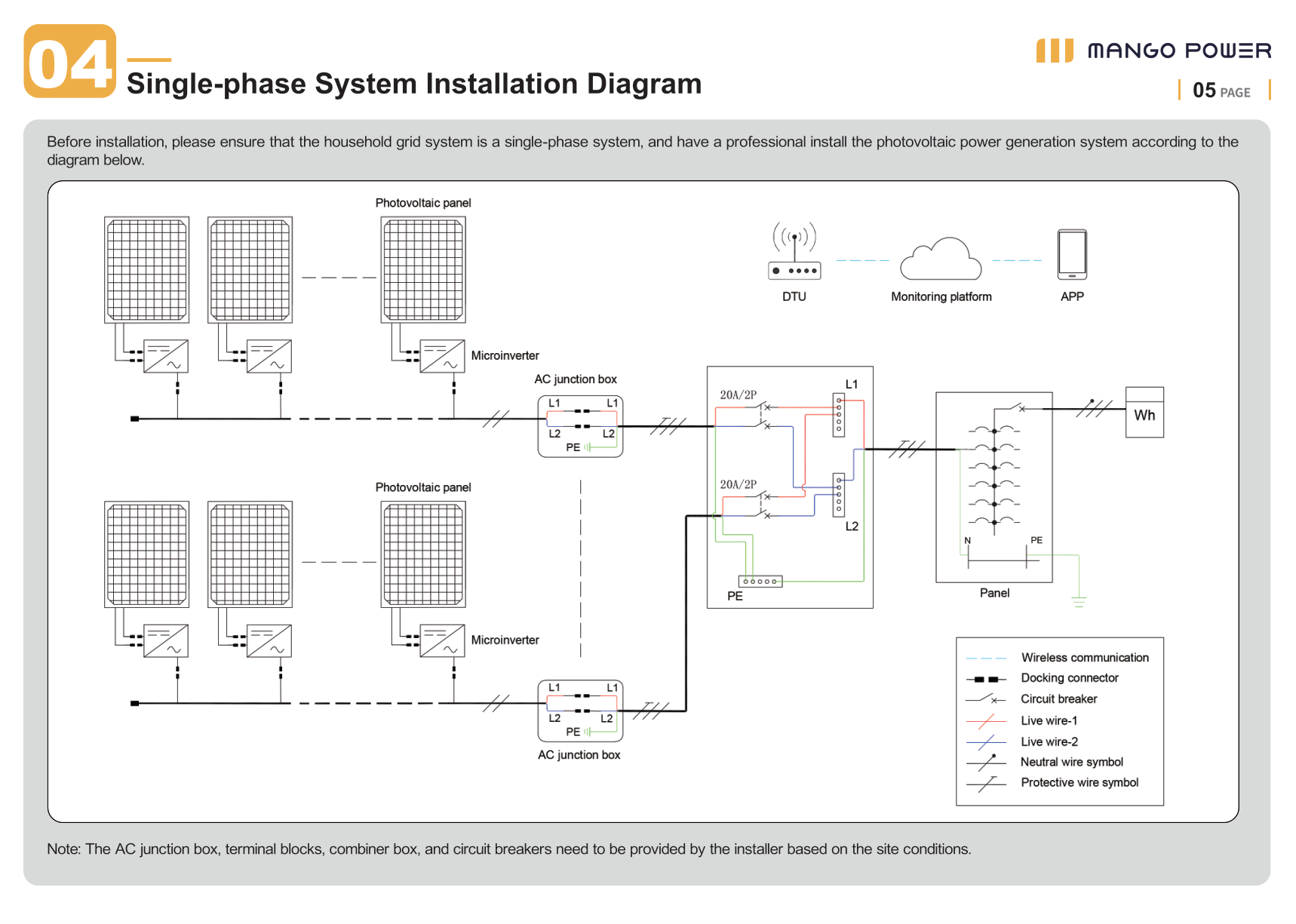
Each branch ends at an AC junction box (L1, L2, PE), then a combiner box with a 20A/2P circuit breaker per branch, then the main panel and utility meter. The DTU communicates wirelessly with the microinverters and the monitoring platform.
Three-phase
Section titled “Three-phase”Before installation, confirm the household grid is a three-phase system. Have a professional install the PV system according to this diagram.
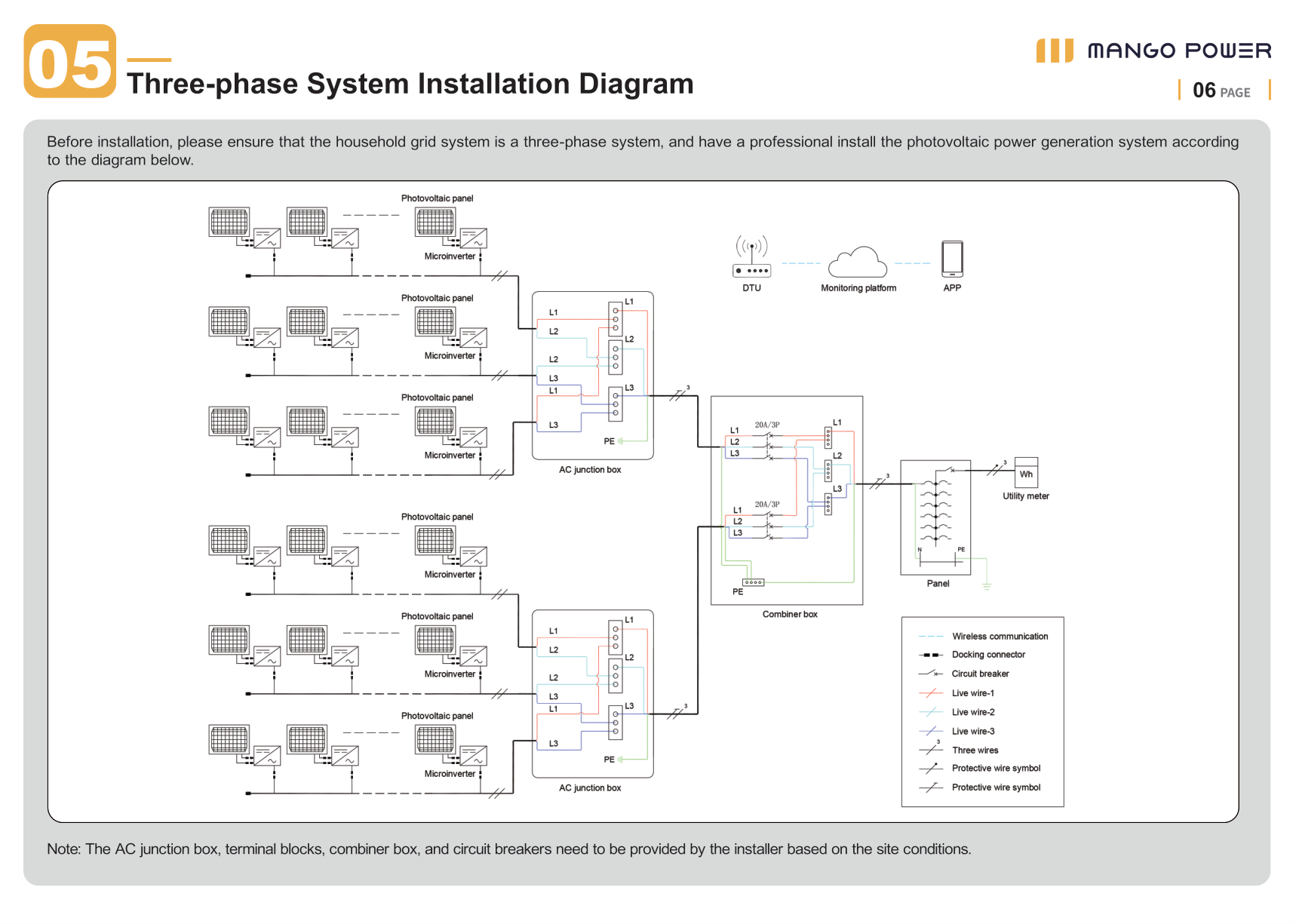
Each branch ends at an AC junction box (L1, L2, L3, PE), then a combiner box with a 20A/3P circuit breaker per branch, then the main panel and utility meter.
SN map
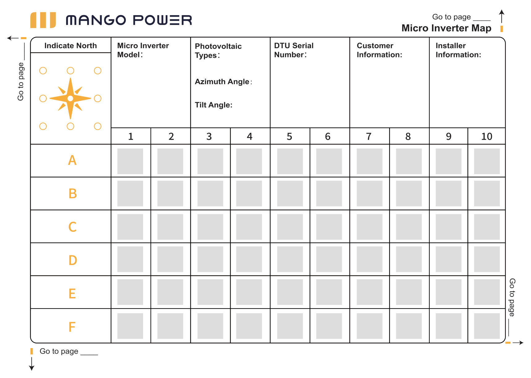
Section titled “SN map”Print this map, mark north, and attach SN labels in installation order.