

User Manual
Installation, operation, maintenance, settings, and configuration must be performed by qualified personnel with electrician certificates. Turn power off before wiring. Ground the equipment. Keep the unit out of direct sun, humidity, and rain. Keep children away. Surrounding clearance ≥400 mm; height off the ground ≥1000 mm. Electrical work must follow local national standards.
Do not operate switches with wet hands. Do not remove the rear bottom plate while circuits are live. Do not touch uninsulated wires. Do not place objects on top of the product. Do not place flammable or explosive materials nearby. Do not modify critical components. Do not use damaged wires.
Ratings are in Specifications.
Installation materials
Section titled “Installation materials”Power cables: 6 AWG black, white, and green-yellow silicone; 12 AWG black and white silicone.
Tools: power drill, screwdriver, insulated gloves.
Wall mounting
Section titled “Wall mounting”- Mark three fixing holes. Drill, insert expansion plugs, and screw a self-tapping screw into the top hole.
- Hang mPanel Pro on the top screw so the lower holes align. Insert and tighten the remaining two screws.
Wiring
Section titled “Wiring”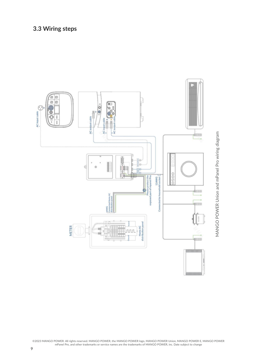
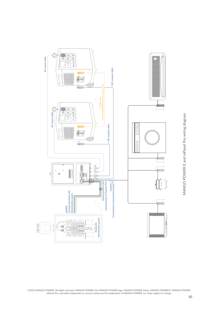
- Open the bottom cover and remove the inner protective cover. Fit prepared silicone cable into the protective tube and protect exposed wires outside the panel.
- 6 AWG from the home AC distribution box to mPanel Pro AC input: black to L1/L2, white to N, yellow-green to PE.
- 12 AWG black to load input hot: L1/L2.
- 12 AWG white to load input neutral: N.
- Refit and tighten the protective cover.
- Connect Union or E with the AC input and AC output cables.
Mango Power Union
- AC input cable: mPanel Pro backup input to Power Home 40 A home-backup outlet or Move 30 A AC outlet. If only Power Move or Power Home is available, connect only to Backup Input-1.
- AC output cable: Output-1 / Output-2 to Power Home or Power Move grid AC input.
One Mango Power E
- AC input cable: Backup Input-1 to the E 30 A AC outlet.
- AC output cable: Output-1 / Output-2 to E GRID AC INPUT.
Two Mango Power E
Connect the two E units with the E-Link cable, then use the AC input and AC output cables on the input/output ports.
Backup mode
Section titled “Backup mode”After install, turn on backup mode on Union or E. Use the knob to switch Backup and Grid.
- Turn the knob to backup, then turn on the grid breaker. The output port can charge Union or E. Turn on the output breaker so Union or E can supply the load. L1-N and L2-N can output four 120 V circuits.
- Two E units in parallel can output two L1-L2-N 240 V split-phases. With backup mode on, only discharge is allowed, not charging. To charge, turn off backup mode on the E units.
- To stop supplying the load, turn off the output breaker as needed.
Grid mode
Section titled “Grid mode”- Turn the knob to grid, then turn on the grid breaker. Utility power supplies the load, Union, or E. L1-N and L2-N can output four 120 V circuits; L1-L2-N can output 240 V.
- To stop, turn off output as needed, or use the grid breaker to cut utility input.